Why “400–6000 MHz / 350 W” Is a System Requirement—Not Yet a Module Specification
A requirement such as:
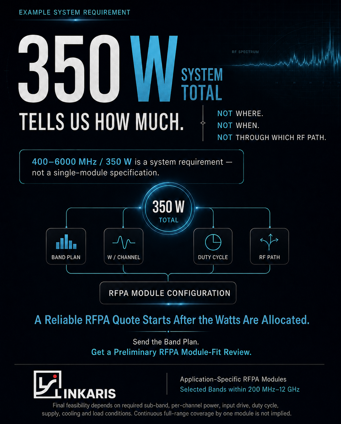
400–6000 MHz / 350 W system total
provides two useful pieces of information: a broad frequency scope and an aggregate power target.
However, it does not yet define an RF power amplifier module.
From an RFPA engineering perspective, 350 W is a system-level quantity, not an architecture. It does not tell us:
- where the 350 W must be measured;
- how the power is divided among frequency channels;
- whether those channels operate simultaneously or sequentially;
- or how many independent RF paths the system contains.
Until these questions are answered, it is not possible to determine the required module count, per-module output power, power-supply capacity, cooling load or RF switching structure.
The engineering process must therefore move from:
Total system power
to:
Power allocated by sub-band, channel and operating condition
1. Why “350 W Total” Is Ambiguous
The phrase 350 W system total may describe several different system conditions.
It could mean:
- one RF path delivering 350 W;
- four channels whose rated powers add up to 350 W;
- several channels with a maximum combined simultaneous output of 350 W;
- switched channels that never transmit at the same time;
- peak RF power in a pulsed system;
- or power measured at the final system output after filters, switches and cable losses.
These interpretations are not interchangeable.
For example, an equal four-channel allocation would theoretically give:
350 W ÷ 4 = 87.5 W per channel
But this is only an illustration. It cannot be assumed unless the system designer confirms that:
- all four channels require equal power;
- all channels operate under the same conditions;
- and 350 W is defined at the same reference point for every path.
A practical system may instead require an uneven allocation:
| Channel | Assigned power |
|---|---|
| Band A | Higher-priority output |
| Band B | Medium output |
| Band C | Lower output |
| Band D | Standby or intermittent output |
The architecture must follow the real allocation—not a convenient mathematical split.
2. Define the RF Power Reference Plane
Before allocating watts, the project must define where the specified power applies.
Possible RF power reference planes include:
- RFPA module output;
- output after the isolator;
- output after the band filter;
- output after an RF switch;
- output after a combiner;
- system RF connector;
- or antenna input.
This distinction matters because every component between the RFPA and the final load introduces some amount of insertion loss.
For one channel, the required RFPA output can be represented conceptually as:
Required PA output = target power at the reference plane + downstream path loss + design margin
In logarithmic units:
PPA,out (dBm) = Ptarget (dBm) + Lpath (dB) + Mmargin (dB)
If the customer requires a certain power at the antenna interface, the RFPA may need to produce more power upstream to compensate for:
- filter loss;
- isolator loss;
- RF switch loss;
- cable and connector loss;
- coupler loss;
- and other passive-path losses.
Without a defined reference plane, the same “100 W per channel” statement can produce different amplifier requirements.
3. Divide the Frequency Range into Real Sub-Bands
A range such as 400–6000 MHz should not automatically be treated as one continuous RFPA operating band.
The system designer should first convert the broad range into a practical band plan.
A preliminary band-plan table may look like this:
| RF path | Actual sub-band | Required bandwidth | Target output | Operation |
|---|---|---|---|---|
| Channel A | Project-defined | TBD | TBD | Simultaneous / switched |
| Channel B | Project-defined | TBD | TBD | Simultaneous / switched |
| Channel C | Project-defined | TBD | TBD | Simultaneous / switched |
| Channel D | Project-defined | TBD | TBD | Simultaneous / switched |
Each sub-band may require a different combination of:
- power device;
- RF matching network;
- gain target;
- filter;
- RF connector;
- mechanical layout;
- and thermal structure.
A product portfolio may support selected project bands across a broad frequency range, but this does not imply that one module continuously covers the full range at the same output power.
The relevant engineering question is therefore not:
Can one amplifier produce 350 W from 400 to 6000 MHz?
It is:
What are the actual sub-bands, and what output is required from each RF path?
4. Allocate Power Per Channel
Once the sub-bands are defined, the total power requirement must be converted into a channel power matrix.
A useful allocation table should include:
| Channel | Frequency band | Required power | Reference plane | Duty cycle | Simultaneous? |
|---|---|---|---|---|---|
| A | Defined sub-band | XX W | Defined point | XX% | Yes / No |
| B | Defined sub-band | XX W | Defined point | XX% | Yes / No |
| C | Defined sub-band | XX W | Defined point | XX% | Yes / No |
| D | Defined sub-band | XX W | Defined point | XX% | Yes / No |
The word total must also be qualified.
Rated total power
The sum of the rated output of all installed RFPA modules.
Maximum simultaneous RF power
The highest combined output when all permitted channels operate at the same time.
Time-averaged RF power
The average RF output after duty cycle and operating sequence are considered.
These three values may be very different.
For example, four installed modules could have a combined rated power of 350 W while the control logic allows only two channels to transmit simultaneously. In that case, the RFPA module ratings, system power supply and average thermal load should not all be interpreted from the same 350 W figure.
5. Confirm Simultaneous or Switched Operation
Channel timing is one of the strongest architecture drivers.
Simultaneous operation
When multiple RF channels operate at the same time, the system must support their combined:
- RF output;
- DC current;
- heat generation;
- switching isolation;
- and load conditions.
The supply and cooling structure must be sized for the maximum permitted concurrent state—not merely for one channel.
Switched operation
When only one channel operates at a time, the architecture may use:
- independent band-specific modules;
- a controlled RF switching network;
- shared downstream components where technically appropriate;
- or different thermal and supply assumptions.
However, switched operation still requires clarification of:
- switching sequence;
- transition time;
- maximum dwell time;
- channel priority;
- and whether short overlap between channels is possible.
A system with four channels operating sequentially is fundamentally different from a four-channel system operating continuously and simultaneously, even when both are described as “350 W total.”
6. Convert the Power Matrix into an RFPA Architecture
After the band plan, reference plane, per-channel power and operating sequence are known, the requirement can be converted into a preliminary RFPA architecture.
The engineering review should determine:
- how many RFPA modules are required;
- which frequency band belongs to each module;
- the required output power of each module;
- whether modules are independent, switched or combined;
- which filters and isolators are required;
- where power monitoring is needed;
- what RF interfaces are used;
- and how the modules connect to the system load.
A simplified architecture decision may follow this logic:
| Requirement input | Architecture decision |
|---|---|
| Number of active sub-bands | Number of RF paths or band-specific stages |
| Power required per channel | Output rating of each RFPA module |
| Simultaneous channel count | Combined DC and thermal design point |
| RF reference plane | Required PA output headroom |
| Downstream losses | Module output adjustment |
| Channel isolation requirement | Filter, isolator and switching structure |
| Mechanical constraints | Module dimensions and placement |
| Monitoring requirement | Coupler, detector or control interface |
The output of this stage is not simply a product model number.
It is a preliminary system-to-module mapping:
Band plan → Per-channel power → RF path → RFPA module configuration
7. Secondary Constraints After Power Allocation
Power allocation determines the basic architecture, but it does not complete the engineering review.
Several secondary conditions must still be verified.
Input drive
The available RF input level must be sufficient for the selected module gain to reach the target output. Each channel may have a different source or driver-stage condition.
Power supply
The available voltage, maximum current and transient capability must support the maximum simultaneous operating state—not only nominal single-channel operation.
Thermal conditions
Duty cycle, RF efficiency, mounting interface, cooling structure and ambient temperature determine whether the allocated power can be maintained reliably.
Load and VSWR
The expected antenna or load mismatch must be defined so that isolator requirements, reflected-power monitoring and protection logic can be evaluated.
These parameters should confirm or modify the architecture after power allocation. They should not replace the initial need to define the power matrix.
8. Determine Whether the Requirement Is Ready for Quotation
Not every RFPA inquiry is ready for quotation at the same stage.
A useful review process can classify the requirement into three levels.
Level 1: Not ready for architecture review
The request contains only a broad frequency range and total wattage.
Example:
400–6000 MHz, 350 W. Please quote.
Missing information includes the sub-band plan, power per channel, reference plane and operating sequence.
Level 2: Ready for preliminary module-fit review
The customer has defined:
- actual sub-bands;
- output power per channel;
- reference plane;
- simultaneous or switched operation;
- and basic input, supply, duty-cycle and cooling conditions.
At this stage, a preliminary architecture can be evaluated.
Level 3: Ready for technical quotation
The RF, DC, thermal, mechanical, interface and load conditions are sufficiently defined to support a project-specific configuration and quotation.
Even at this stage, a preliminary fit should not be interpreted as a final performance commitment. Final feasibility remains subject to engineering verification, module design and validation conditions.
From a Power Number to a Module Architecture
A reliable RFPA project should follow this sequence:
System requirement
↓
RF power reference plane
↓
Actual sub-band plan
↓
Power allocation per channel
↓
Simultaneous or switched operation
↓
RFPA architecture
↓
Input, supply, thermal and load verification
↓
Technical quotation
The key conclusion is simple:
350 W tells us how much power the system may require. It does not yet tell us how that power should be built.
A reliable quotation starts after the watts have been allocated to real RF channels and operating conditions.
Start with the Band Plan
For a preliminary RFPA module-fit review, provide:
- actual operating sub-bands;
- required power per channel;
- RF power reference plane;
- simultaneous or switched operating logic;
- duty cycle;
- available input drive;
- supply voltage and current;
- cooling conditions;
- and expected load or VSWR range.
Linkaris evaluates application-specific RFPA module configurations for selected project bands within 200 MHz–12 GHz.
Coverage is project-specific. Continuous full-range coverage by one module is not implied.
Send the band plan and channel power allocation.
Receive a preliminary RFPA architecture review.
 Chat with us on Telegram
