Why fault observability, protection-state monitoring, and serviceability should influence RF power amplifier selection
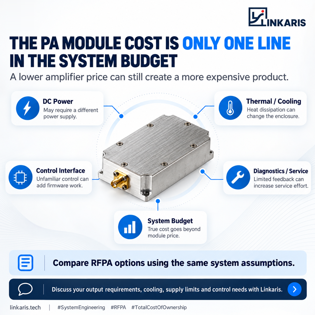
1. A Lower Module Price Does Not Guarantee Lower Engineering Effort
An RF power amplifier can meet its required frequency range, output power, and gain specifications—and still become difficult to maintain after integration.
Consider a system operating normally during initial testing.
The RFPA delivers the expected output. The DC supply appears stable. The cooling arrangement satisfies the initial operating conditions.
Several weeks later, the system reports an unexpected reduction in RF output.
The engineering team now faces several possible explanations:
Was the input drive reduced? Did the DC voltage drop under load? Was thermal protection activated? Did reflected power trigger an output limitation? Or did the amplifier itself develop a fault?
Without sufficient diagnostic information, these possibilities can produce similar symptoms.
The engineering challenge is no longer simply achieving the required RF output.
It is identifying which part of the system changed—and obtaining enough evidence to investigate the cause without unnecessary hardware replacement.
This is where an apparently economical RFPA can introduce substantial hidden engineering costs.
The module price is visible in the purchasing quotation. The time required to identify an intermittent fault often is not.
2. The RFPA Is Connected to Several Diagnostic Boundaries
An RFPA operates within a network of electrical, RF, thermal, and control interfaces.
Each interface can influence amplifier behavior, but not every system exposes enough information to distinguish one failure mechanism from another.
For example, a reduction in RF output power could result from insufficient input drive or an abnormal antenna/load condition.
A DC supply problem may appear only during high-current operation.
An inadequate thermal interface may allow acceptable operation during a short test but cause protective action during extended transmission.
The central engineering concept is fault observability.
Fault observability describes how effectively the available measurements and status information allow engineers to distinguish internal amplifier behavior from conditions originating elsewhere in the system.
It does not require every parameter to be monitored continuously.
It requires the right information to be available when an abnormal operating condition occurs.
What Should Engineers Be Able to Observe?
| Diagnostic boundary | Useful engineering evidence | What it helps distinguish |
|---|---|---|
| RF input | Input drive level, waveform and operating mode | Insufficient drive versus amplifier-related output changes |
| DC supply | Voltage at PA terminals, load current and transient behavior | Supply limitations versus other RF performance problems |
| Thermal | Baseplate temperature, cooling conditions and thermal alarm state | Temperature-related limitations versus unrelated faults |
| RF output/load | Forward and reflected power, protection indication | Load mismatch or RF output behavior requiring further investigation |
| Control/protection | Enable state, fault flags, shutdown and recovery status | Commanded shutdown versus automatic protective action |
Not all RFPA modules provide these signals internally.
Some measurements must be implemented at the system level, while others may be available through dedicated monitoring or control interfaces.
The engineering objective is to define this diagnostic boundary before the system enters production or deployment.
3. Engineering Example: When a Power Problem Looks Like an RFPA Failure
Consider an illustrative RF system using a nominal 28 V DC power supply.
During initial testing, the RFPA operates correctly.
Under a particular high-current operating condition, however, the RF output becomes unstable.
The system’s main power supply still indicates approximately 28 V.
An engineer who relies only on this measurement may initially suspect the RFPA.
But the voltage at the power supply output is not necessarily the voltage received at the amplifier terminals.
The electrical path between them introduces resistance through cables, connectors, and contact interfaces.
Assume the following illustrative conditions:
- Current during operation: 8 A
- Total series resistance in the supply path: 0.30 Ω
- Nominal supply voltage: 28 V
Using Ohm’s law:
Voltage drop = Current × Resistance
ΔV = 8 A × 0.30 Ω = 2.4 V
Therefore, the amplifier terminals receive approximately:
28 V − 2.4 V = 25.6 V
The same resistance also produces electrical losses:
P_loss = I²R = 8² × 0.30 = 19.2 W
That is 19.2 W dissipated along the supply path rather than delivered to the RFPA.
Whether the resulting voltage reduction affects RF output depends on the amplifier’s actual supply tolerance, operating point, and protection configuration.
Nevertheless, this example demonstrates a critical diagnostic distinction.
A voltage measured at the power supply is not automatically proof of adequate voltage at the RFPA.
Without measurements at the correct electrical reference point, the engineering team may replace a functioning module while leaving the actual integration problem unresolved.
The additional expense comes from troubleshooting effort, replacement handling, repeated qualification, and potential service interruptions—not necessarily from the amplifier itself.
4. Protection Circuits Are More Valuable When Their Behavior Is Understandable
RF power amplifiers may incorporate protective functions addressing over-temperature, excessive current, abnormal supply conditions, or load mismatch.
These functions help reduce the risk of damage under certain operating conditions.
However, protection and diagnostics are not the same engineering function.
A module may shut down or reduce output as intended while providing insufficient information for the host system to determine why that action occurred.
For an integrator, several questions become important.
Did the module enter a temperature-related protection state?
Was the output limited because of abnormal reflected power?
Did the host controller disable the amplifier?
Was the protection event temporary, or did it require an explicit reset?
The answers influence how the surrounding system should respond.
Protection Status Should Support Fault Isolation
A useful integration design establishes a relationship between operating measurements, protective actions, and recovery behavior.
For example, if RF output decreases while the input drive remains consistent, forward/reflected power information and protection status can help narrow the investigation.
Where directional-coupler measurements are available and properly calibrated, the ratio of reflected to forward power can also provide an indication of load mismatch.
The magnitude of the reflection coefficient is:
|Γ| = √(P_reflected / P_forward)
The corresponding voltage standing wave ratio is:
VSWR = (1 + |Γ|) / (1 − |Γ|)
These relationships are useful only when the measurement reference plane, calibration, and operating conditions are correctly understood.
They also do not independently establish the cause of an RFPA protection event.
A strong diagnostic design combines RF measurements with available control and protection information rather than relying on a single parameter.
5. Monitoring Speed Matters as Much as Monitoring Availability
Adding a digital monitoring interface does not automatically solve the diagnostic problem.
The sampling rate and event-recording behavior must match the phenomena engineers need to investigate.
Consider two different operating events.
The first is a gradual temperature increase during extended operation.
The second is a short DC voltage disturbance occurring during a high-current transition.
These events happen on different timescales.
Relatively slow temperature monitoring may be sufficient to reveal a sustained thermal trend.
The same monitoring interval may completely miss a brief voltage disturbance.
A host controller that polls amplifier status periodically could receive normal values before and after an event without capturing the abnormal condition itself.
This creates an important distinction between three functions:
Measurement: What physical or operating parameter is being observed?
Protection: How quickly does the hardware react when a critical condition occurs?
Diagnostic reporting: What information remains available after that event?
Fast electrical protection may require local hardware mechanisms that operate independently of slower software communication.
For meaningful fault investigation, an appropriate design may also require latched fault indications, event counters, or externally captured measurements.
The specific approach depends on the module architecture and system requirements.
This is particularly relevant for RF systems operating with changing duty cycles or intermittent high-current loads.
A status interface is useful only when its measurement resolution, timing, and reporting behavior are suitable for the intended diagnostic task.
6. Serviceability Begins with the Information Available at the Module Boundary
When engineers evaluate an RFPA, they commonly focus on whether it can deliver the required performance.
After installation, a different requirement becomes important:
Can the system identify an abnormal operating condition without immediately removing the amplifier?
A serviceable architecture should make it possible to establish an operating record around a fault.
That record may include the operating frequency, commanded RF input, duty cycle, supply conditions, temperature, forward/reflected power, and relevant protection states.
The actual information available will depend on the module and external instrumentation.
The objective is not to guarantee that every fault can be diagnosed remotely.
Instead, it is to reduce unnecessary diagnostic uncertainty.
A system with appropriate monitoring may allow an engineer to distinguish a suspected RFPA hardware problem from an upstream drive issue, a supply-distribution problem, or a load-related protection event.
A system without those observations may require repeated laboratory tests or physical module replacement before the investigation can progress.
This is where control-interface decisions have consequences beyond firmware development.
Interfaces influence not only how the amplifier is enabled or configured, but also how its behavior can be understood throughout the equipment lifecycle.
7. How Linkaris Approaches RFPA Integration Requirements
At Linkaris, RFPA evaluation is not limited to a target frequency and output-power rating.
The operating conditions and module interfaces must also be considered.
For project-specific evaluation, the discussion can include the available DC supply, expected operating mode, cooling arrangement, RF input conditions, mechanical interfaces, and control requirements.
Where monitoring and protection functions are relevant, their availability and integration feasibility should be reviewed for the specific RFPA configuration.
Certain configurations may support digital status monitoring, including RS485-based communication where applicable. The information exposed, communication behavior, and protection functions require model-specific technical confirmation.
The purpose of this review is not to turn the RFPA supplier into the designer of the entire host system.
It is to establish clearer module-level operating boundaries and help engineering teams determine which information must be obtained from the amplifier and which must be measured elsewhere.
For system integrators, these distinctions can reduce uncertainty during prototype evaluation, integration, and subsequent maintenance.
They also make it easier to compare RFPA options against the same diagnostic and operational requirements.
8. The Better Procurement Question
Two RFPA modules may appear similar when their datasheets are compared.
Both may satisfy the requested frequency band.
Both may provide the required RF output power.
Both may fit within the available mechanical space.
One may also have a lower purchasing price.
But the technical comparison is incomplete until engineers understand how each module behaves under abnormal operating conditions—and what evidence the system can obtain when something changes.
The relevant comparison is not simply the number of diagnostic features listed.
It is whether the available features, external measurements, and interface definitions are sufficient for the system’s fault-isolation requirements.
A lower module price may be a genuine advantage when these requirements are already satisfied.
When they are not, the resulting diagnostic limitations may impose costs that were never visible in the purchasing quotation.
The most economical RFPA is not necessarily the cheapest module or the module with the most monitoring features. It is the option whose RF performance, operating boundaries, and diagnostic interfaces fit the actual system requirements.
Discuss Your RFPA Integration Requirements with Linkaris
Are you evaluating an RF power amplifier for a new design, an existing system, or a replacement project?
Linkaris supports project-oriented RFPA module evaluation, including the review of operating requirements and relevant integration interfaces.
Share your target frequency band, RF output power, available supply, duty cycle, cooling arrangement, and monitoring or control requirements.
Our team can review the applicable module options and clarify the information needed for further technical evaluation.
Website: https://linkaris.tech/
Contact Linkaris to discuss your RFPA application and integration requirements.
 Chat with us on Telegram
