Review connector orientation, cable space, service access and the thermal interface before closing the enclosure design.
An RF power amplifier module can fit inside an enclosure while its connected cable assembly prevents the lid from closing. A mounting screw may be visible but unreachable with the intended tool. A module may be easy to install before neighbouring assemblies are added, yet difficult to replace afterwards.
These problems arise when length, width and height are treated as the complete mechanical requirement. For RFPA mechanical integration, the review needs to cover the installed assembly and the operations required to assemble, connect and service it. The metal casing and its intended heat path belong in that review too.
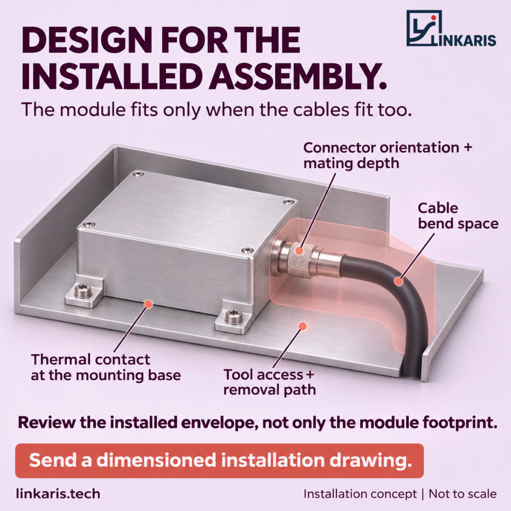
Define the space occupied by the connected assembly
The module outline establishes where the housing can sit. The installed envelope adds everything that extends beyond it: mating connectors, cable exits, cable bends, power and control wiring, clamps and mounting hardware.
Use the intended cable assembly in the installation model wherever possible. Include the connector body, coupling mechanism and any backshell or strain relief. Check surrounding walls, the closed lid and neighbouring equipment against that complete geometry.
For each interface, show the connector location and direction from a common mounting datum. Confirm what the supplier’s outline dimensions include. A housing dimension, a dimension over connector projections and a dimension with the cable connected describe different boundaries.
Specify connector orientation and mating space
A connector needs room for the mating part and for the movement used to connect it. Threaded interfaces also need access to the coupling nut and the specified tightening tool. Review this space with the surrounding hardware installed.
Define the clearance from the module’s mating interface to the nearest obstruction. Then check the selected cable connector’s mated length, the space needed to engage or release it, and the cable exit direction.
A right-angle connector or adapter can change the routing geometry, but it also changes the assembly being evaluated. Confirm its mechanical envelope, RF suitability and availability for the proposed configuration before using it to resolve a space constraint.
Use the selected cable assembly’s bending requirements
Cable clearance depends on the actual cable construction and connector termination. Follow the selected assembly manufacturer’s bend-radius and handling instructions, including any distinction between installation, fixed routing and repeated movement. Avoid forcing a cable into place or using the enclosure lid to hold it in a tight bend. Times Microwave Systems’ installation guidance explains why bending and cable handling affect the transmission line.[1]
Do not apply one generic bend rule to every assembly. Some specialised cable assemblies are designed to bend close behind the connector; that capability must be verified for the selected part.[2] Show the intended bend and support points in the installation drawing so the assembly team can reproduce the route.
Review installation and removal as separate operations
An assembly sequence can conceal an access problem. A module installed into an empty chassis may become inaccessible once a power supply, cable harness or adjacent channel is fitted.
Review the sequence in both directions. Identify when the module is fastened, when each connector is mated, and which components are already present. Then define how the unit will be disconnected, unfastened and withdrawn during service.
The removal path may need more space than the final operating position. Include room for tools, connector release and any movement required before the module clears its mounting features. If other assemblies must be removed first, make that part of the service plan.
Include the metal casing in the thermal review
Linkaris modules use their metal casing for heat dissipation. Mechanical review should therefore consider how the casing is mounted and how heat is intended to leave it in the host product.
Where the design relies on conduction into a chassis or mounting plate, identify the intended contact surface and confirm the required contact area, surface condition, fastening arrangement and interface material, if specified. A bracket that locates the module correctly may still fail to provide the intended thermal contact.
Ampleon’s component mounting guidance describes how gaps, surface irregularities and misalignment can increase thermal interface resistance.[3] This supports the general need to review contact quality; its transistor-package mounting values should not be transferred to a complete Linkaris module.
Confirm the applicable mounting instructions and thermal limits for the selected configuration. Evaluate the host arrangement at the intended RF operating point, duty cycle and ambient conditions. A mechanical fit check alone cannot establish acceptable temperature behaviour.
Turn the drawing into a mechanical acceptance checklist
A useful review records what must be checked and which evidence will close each item. The following checklist can be adapted to the project.
| Review item | Information to define | Evidence to agree |
|---|---|---|
| Module and mounting geometry | Outline, mounting datum, hole locations, fasteners and relevant tolerances | Revision-controlled outline and host installation drawing |
| RF interfaces | Connector type, orientation, mating position and access space | Mated connector geometry and an access check |
| Cable routing | Assembly identity, bend limits, exit direction and support points | Cable specification and installed routing review |
| Power and control wiring | Connector location, harness exit and required clearance | Interface definition and harness layout |
| Assembly and servicing | Tool approach, assembly order, disconnect space and removal path | Demonstrated installation and removal sequence |
| Thermal interface | Casing contact surface and configuration-specific mounting requirements | Mounting definition and thermal validation under agreed conditions |
Keep unresolved items visible. A drawing approval should identify the module revision, cable assembly and host configuration covered by the review. Changes to those items may require the affected checks to be repeated.
Compare the installation effort alongside the footprint
Consider a layout in which a compact module leaves little space between its RF connector and the enclosure wall. The housing fits, but the selected cable cannot follow its permitted route. Moving the module, revising the enclosure or selecting a different qualified cable assembly becomes part of the integration work.
For buyers and system integrators, the useful comparison includes that work: cable sourcing, assembly access, thermal contact and replacement effort. Evaluate the module within the complete installation before treating a smaller housing as a project benefit.
Bring the installation drawing into the RFPA enquiry
When discussing a Linkaris RFPA module, share a dimensioned installation drawing showing the surrounding interfaces. Include the connector direction, intended cable assembly, enclosure boundaries, mounting surface and service access. Add the operating band, required RF output, duty cycle and expected thermal conditions so the mechanical and RF requirements can be reviewed together.
Explain which dimensions are fixed and where changes remain possible. This gives the discussion a concrete basis for evaluating the proposed module and any interface changes. Confirm the available configuration, supporting drawings and validation scope for the selected model.
Planning an RFPA installation?
Send Linkaris your dimensioned installation drawing and intended cable arrangement. Include the mounting surface and removal path so the review covers the connected assembly.
Discuss your RFPA installation requirements with Linkaris
Technical references
- Times Microwave Systems, Making the Connection With Coaxial Cable. Cable installation and bending guidance.
- Times Microwave Systems, IB-086 product information. An example of assembly-specific bending capability.
- Ampleon, AN11183 Mounting and soldering of RF transistors in overmolded plastic packages, Revision 10, Section 9. General thermal-contact principles at component level.
 Chat with us on Telegram
