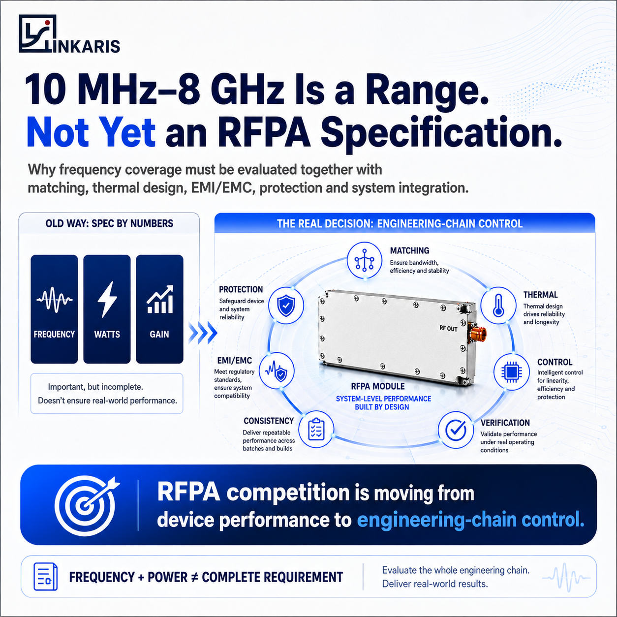
Why RFPA selection must move beyond frequency and watts to matching, thermal design, EMI/EMC, protection and system integration.
A customer asks:
“Can you provide an RF power amplifier from 10 MHz to 8 GHz?”
It sounds like a clear RFPA requirement.
It is not.
A frequency range tells us where the project may operate. It does not tell us what amplifier architecture the system actually needs.
Before selecting or modifying an RFPA, several other questions immediately appear:
- Which sub-bands are actually required?
- What output power is needed in each band?
- What input drive is available?
- Is operation CW, pulsed or intermittent?
- What supply voltage and current are available?
- How will heat be removed?
- What antenna or load conditions will the amplifier see?
- What VSWR conditions must it tolerate?
- What control, monitoring and mechanical interfaces already exist?
Until those conditions are understood:
10 MHz–8 GHz is a frequency range. It is not yet an RFPA specification.
And it should never automatically be interpreted as one amplifier continuously covering the entire range.
The real band plan determines the architecture.
1. Frequency Defines the Operating Space. The System Defines the RFPA.
Frequency is one of the first parameters engineers need.
But it is only the beginning.
Consider two projects operating in the same band.
Both may request the same output power.
Yet one operates intermittently in an open enclosure with strong forced-air cooling, while the other must run continuously inside a compact sealed platform.
The RF requirement may look similar on paper.
The engineering problem is not.
Different operating conditions can change:
- device selection,
- gain architecture,
- power supply requirements,
- heat dissipation,
- protection strategy,
- mechanical design,
- filtering,
- control logic,
- and verification procedures.
This is why a useful RFPA discussion should not begin with:
“Which model covers the frequency?”
It should begin with:
“How will the amplifier operate inside the RF system?”
2. Wider Frequency Requirements Create a Wider Engineering Problem
Broad frequency capability is valuable.
But as the required operating span expands, the engineering challenge does not increase in only one dimension.
Matching
Input and output matching must remain controlled across the required operating bands.
A matching network optimized around one frequency cannot simply be assumed to provide the same behavior elsewhere.
As frequency requirements expand, insertion loss, gain flatness and impedance behavior become increasingly important.
Thermal Design
A module reaching its target RF power during a short bench test does not automatically mean it can sustain that power in the final platform.
Thermal performance depends on:
output power + efficiency + duty cycle + ambient temperature + enclosure + cooling conditions.
That means thermal design cannot be separated from RFPA selection.
Load and Protection
Real systems do not always present an ideal 50-ohm laboratory load.
Antennas, cables, switches, filters and environmental changes can alter the impedance seen by the amplifier.
Reflected power and VSWR therefore become architecture questions—not merely protection features added at the end.
EMI / EMC
Modern RF platforms increasingly combine RF power stages with:
- digital control,
- power electronics,
- receivers,
- filters,
- switching networks,
- monitoring circuits,
- and multiple RF channels.
The amplifier must coexist with all of them.
As system density increases, shielding, unwanted coupling, grounding, filtering and electromagnetic compatibility become part of the RFPA integration problem.
Control and Monitoring
Enable logic, temperature feedback, alarms, power detection and communication interfaces may look secondary during initial sourcing.
They become critical when the RFPA enters a real OEM platform.
A module that cannot communicate or interact correctly with the host system may force additional redesign even when its RF performance looks acceptable.
3. The RF Industry Is Moving Beyond the Headline Specification
Traditionally, many RFPA sourcing discussions start with three numbers:
Frequency.
Power.
Gain.
Those numbers remain important.
But recent developments across the RF and microwave component ecosystem show a broader direction.
Engineering attention is increasingly distributed across the entire RF chain—from power devices and couplers to EMI/EMC components, connectors, monitoring and test equipment.
The implication for RFPA suppliers is important.
The next stage of competition will not be based only on the transistor or the maximum wattage on a datasheet.
It will increasingly depend on the ability to control the complete engineering chain:
RF Performance → Matching → Protection → Thermal → EMI/EMC → Control → Verification → Consistency
This leads to a different way of looking at RFPA capability:
The next RFPA differentiation is engineering-chain control, not just transistor power density.
A high-performance RF device remains important.
But a powerful transistor does not automatically create an integration-ready amplifier.
The engineering around it does.
4. A Successful Prototype Is Not the Same as a Controlled RFPA Platform
One of the most important distinctions in RFPA projects is the difference between:
making one unit work
and
building an architecture that can be repeatedly delivered.
A prototype may demonstrate the required output power under controlled laboratory conditions.
The next questions are harder:
- Does performance remain stable as temperature changes?
- Does the amplifier behave correctly under realistic load mismatch?
- Is gain sufficiently repeatable?
- Can the cooling solution support the intended duty cycle?
- Can the power supply handle the required current margin?
- Can production units remain sufficiently consistent?
- Can the same architecture be maintained when the customer moves from prototype to volume delivery?
For OEMs and system integrators, this transition matters more than a single successful test result.
Because the real product is not just RF power.
It is repeatable RF power under known operating conditions.
5. Broad Frequency Requirements Should Be Decomposed Before RFPA Selection
Instead of sending only:
“We need 100 W from X MHz to Y GHz.”
A more useful initial RFPA requirement should include the following.
1. Target Sub-Band or Band Plan
Which portions of the total frequency range are actually required?
Are they operated independently, sequentially or simultaneously?
2. Required Output Power
What output power is needed in each operating band?
3. Input Drive
What RF level is available from the signal source or driver stage?
This determines the required gain budget and whether another driver stage is necessary.
4. Supply Conditions
What voltage and current can the host system provide?
Available current margin can become critical during high-power operation.
5. Duty Cycle
Is the RFPA operating:
- CW,
- pulsed,
- or intermittently?
The answer can substantially change the thermal architecture.
6. Cooling Environment
What cooling method is available?
Heatsink?
Forced air?
Conductive cooling?
A customer-defined cold plate?
The final RFPA architecture must fit the real thermal path.
7. Load / VSWR Conditions
What antenna, cable and RF path will the amplifier see?
What mismatch conditions should the module tolerate?
8. Mechanical and Control Constraints
Dimensions, connectors, mounting method, enable logic and monitoring interfaces may determine whether an otherwise suitable RFPA can actually be integrated.
9. Project Stage
Is the customer working on:
a new prototype, an existing-platform redesign, or a second-source qualification?
The correct engineering path may be different for each.
6. Do Not Customize What Does Not Need to Be Customized
A non-standard requirement does not automatically require a completely new RFPA.
This is another important distinction.
There are normally several possible engineering paths.
Existing RFPA Platform
If an existing validated module already satisfies the RF, thermal and mechanical conditions, additional redesign may create unnecessary cost and risk.
Modified-Standard RFPA
Sometimes the RF core remains suitable while the customer requires controlled modifications such as:
- gain,
- supply,
- connector,
- control interface,
- mechanical structure,
- or cooling conditions.
In this case, controlled modification may be more efficient than starting from zero.
Project-Specific RFPA
A new architecture becomes appropriate when the existing RF platform can no longer satisfy the actual frequency, power, thermal or system conditions.
The objective should therefore not be:
maximum customization.
It should be:
the least-complex validated architecture that reliably fits the system.
That reduces both technical risk and unnecessary development work.
7. What OEMs and System Integrators Are Really Buying
A customer may appear to be purchasing:
a frequency band + an output-power level.
But that is rarely the complete buying decision.
The customer is also asking:
- Will it integrate?
- Will it overheat?
- Will it survive realistic load conditions?
- Will the prototype and production unit behave consistently?
- Can the supplier respond when the system changes?
- Can the architecture be maintained throughout the project?
This changes the commercial meaning of RFPA engineering.
The lowest-risk amplifier is not necessarily:
the widest-band module,
the highest-power module,
or the lowest-priced module.
It is the architecture that fits the customer’s system with the least unnecessary uncertainty.
RFPA selection should remove integration uncertainty—not move it downstream.
That is where engineering capability becomes commercial value.
8. From Frequency Coverage to Engineering Control
Linkaris works with RFPA requirements across multiple project frequency bands, including projects extending from approximately 10 MHz to 8 GHz.
But the value of that frequency experience is not the ability to place one large range on a datasheet.
The more important capability is knowing when different frequencies, powers and operating conditions require different engineering paths.
For each project, the real question remains:
What RFPA architecture best fits the customer’s RF chain?
That requires looking beyond frequency and watts.
It requires evaluating:
Band Plan
→ Output Power
→ Input Drive
→ Supply
→ Duty Cycle
→ Cooling
→ Load / VSWR
→ Control
→ Mechanical Integration
→ Verification
Only theOnly then does a frequency requirement become an engineering specification.
10 MHz–8 GHz Is a Range.
Engineering Conditions Turn It Into an RFPA Specification.
If you are evaluating a new RFPA, replacing an existing module or qualifying a second source, send Linkaris:
- Target frequency band / band plan
- Required output power
- Input drive
- Supply voltage and current
- CW / pulsed / intermittent operation
- Duty cycle
- Cooling conditions
- Load / VSWR conditions
- Mechanical and control requirements
- Current project stage
We can first review whether an existing, modified-standard or project-specific RFPA architecture is the more appropriate path.
Start with the system. Then select the RFPA.n does a frequency requirement become an engineering specification.
 Chat with us on Telegram
