A UAV communication problem is often described in one sentence:
| “We need more transmit power.” |
But increasing the PA output rating does not always produce a more stable command link, longer telemetry range, or better video transmission.
The limitation may be inside the power amplifier. It may also come from insufficient input drive, voltage drop, thermal accumulation, RF cable loss, filtering loss, antenna mismatch, or the way the PA is integrated into the platform.
This article helps UAV system developers determine:
- where the RFPA belongs in the communication architecture;
- which PA priorities change between command, telemetry and video links;
- whether increasing wattage is likely to solve the real problem;
- which system parameters should be confirmed before selecting a module.
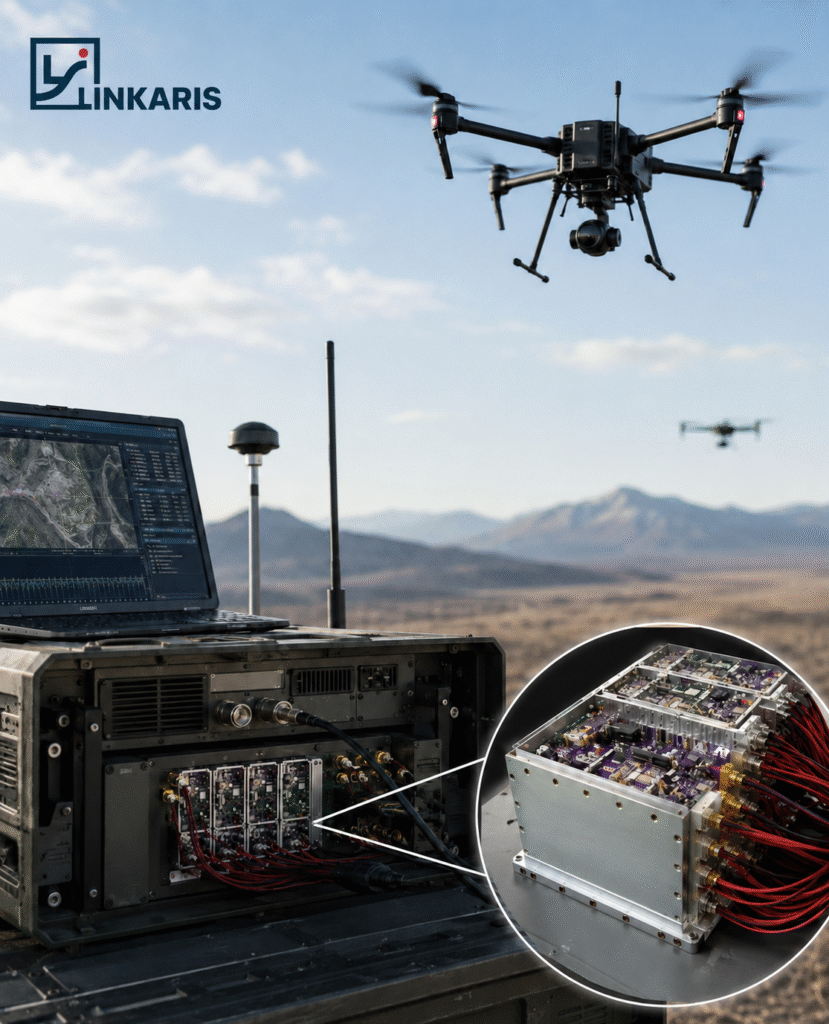
1. Where the PA Sits in a UAV Communication System
A simplified UAV transmitter chain can be represented as:
| Signal Source → Driver → RF Power Amplifier → Filter/Protection → RF Cable → Antenna |
The PA increases the signal from the driver stage to the required RF output level.
However, the power measured at the PA connector is not necessarily the power that reaches the antenna. Filters, switches, connectors and cables introduce loss. Antenna mismatch can also cause reflected power. This means a system can use a higher-rated PA and still deliver less usable RF power than expected.
The first engineering question should therefore not be:
| “What is the highest-power module available?” |
It should be:
| “Where is power being lost or becoming unstable in the complete transmitter chain?” |
2. Command, Telemetry and Video Links Do Not Need the Same PA
Command-and-control uplink
A command link usually prioritizes:
- stable RF output;
- predictable activation and control;
- sufficient operating margin;
- reliable operation during mission-critical commands;
- compatibility with the ground-station power supply and antenna.
The highest possible output is not always necessary. Controlled and repeatable output may be more valuable.
Telemetry link
Telemetry may operate from the UAV to the ground station or in a bidirectional architecture.
An airborne telemetry PA usually requires:
- high efficiency;
- low DC consumption;
- compact dimensions;
- limited heat generation;
- compatibility with the onboard supply;
- stable operation under vibration and changing orientation.
Video and high-data-rate links
Video transmission can place greater importance on:
- linear output power;
- gain behavior;
- signal bandwidth;
- modulation quality;
- thermal stability during longer transmission periods.
A PA that reaches a strong saturated-power figure may still be unsuitable when the application requires linear amplification of a wider-band signal.
3. Ground-Based and Airborne PA Requirements Are Different
| PA position | Main priorities |
| Ground control station | Higher available output, longer operating time, stronger cooling and easier maintenance |
| Airborne UAV platform | Low size, weight and power consumption; high efficiency; controlled thermal load |
| Mast-mounted RF unit | Shorter feeder path, outdoor protection and antenna proximity |
| Relay or repeater | Bidirectional operation, extended operating time and thermal stability |
| Payload transmitter | Signal linearity, onboard-supply compatibility and data-link requirements |
A module designed for a ground station should not automatically be placed on an aircraft. Likewise, a lightweight airborne PA may not be suitable for continuous high-power operation in a fixed ground system.
4. Four Reasons More PA Power May Not Improve the Link
Insufficient input drive
The PA can only reach the expected output when the preceding signal source or driver provides the required input level. A high-power PA with insufficient drive may appear to be underperforming even though the module itself is operating normally.
Unstable power supply
Voltage drop, current limitation, cable resistance, ripple or transient behavior can reduce output or trigger instability. The supply must be evaluated under real RF operation, not only when the system is idle.
Restricted thermal path
A module may reach the required power during a short test but drift after heat accumulates. Ground enclosures, airborne platforms and compact portable systems all create different cooling conditions.
Loss or mismatch after the PA
Filters, switches, connectors, feeder cables and the antenna system can reduce delivered power. Replacing the amplifier with a larger model may temporarily mask these losses without correcting the underlying RF-chain problem.
5. UAV RFPA Integration Readiness Check
Before selecting or customizing a PA module, confirm the following:
| Parameter | Information required |
| Frequency | Exact start and stop frequency or required sub-band |
| Output | Required power at the PA output or antenna input |
| Input drive | Available RF input power from the driver |
| Signal | CW, pulsed, modulated or intermittent |
| Supply | Voltage, available current and stability |
| Duty cycle | Transmission duration and operating pattern |
| Cooling | Conduction, forced air or other thermal path |
| RF load | Filter, cable, antenna and expected VSWR |
| Installation | Ground, airborne, relay or external RF unit |
| Mechanical | Size, weight, connector and mounting limits |
These parameters make it possible to distinguish between:
- a standard module;
- a modified existing module;
- an application-specific RFPA configuration;
- a system problem that may need to be corrected outside the PA.
6. What an Initial Linkaris Review Should Provide
A useful RFPA review should not end with a product list.
Based on the available system information, an initial review can identify:
- the likely PA architecture class;
- whether the requirement is suited to a ground or airborne configuration;
- whether available input drive is sufficient;
- potential supply and thermal constraints;
- missing information that should be measured;
- whether standard, modified or customized module evaluation is appropriate.
The purpose is not to recommend the highest wattage.The purpose is to identify a module direction that can be tested and integrated under the actual UAV system conditions.
 Chat with us on Telegram
