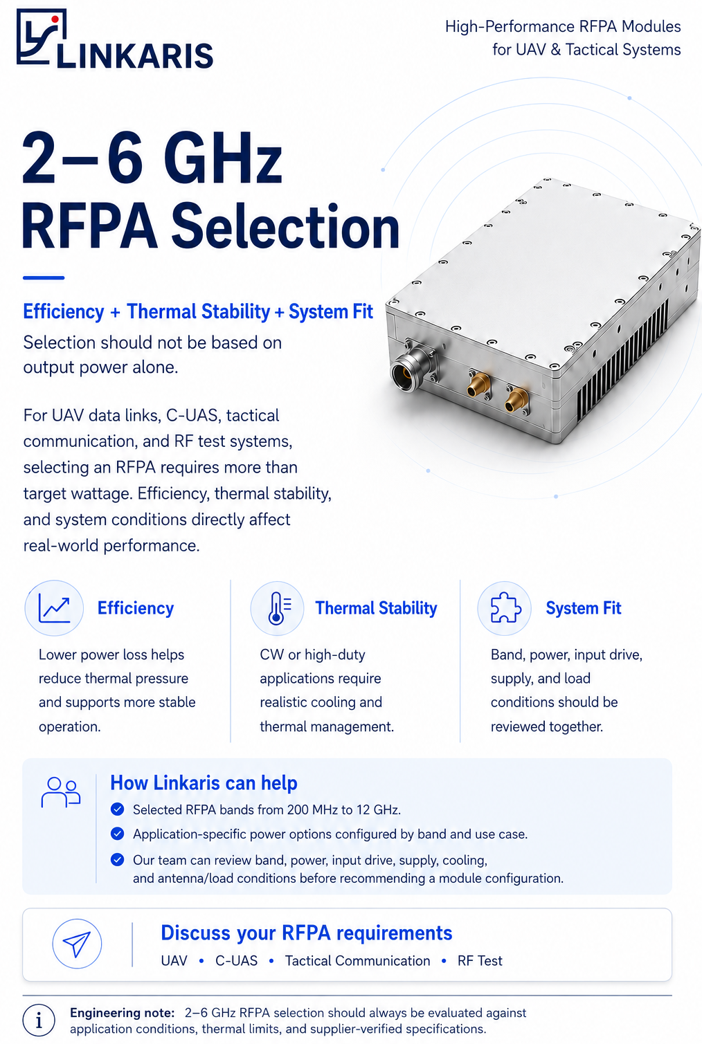
A 2-6 GHz RFPA module should not be selected only by frequency range and output power.
For UAV data links, C-UAS RF systems, tactical communication platforms, and RF test environments, the same 2-6 GHz range can create very different engineering requirements.
A UAV platform may care most about efficiency, size, supply current, and cooling space. A C-UAS system may focus more on duty cycle, thermal margin, load behavior, and protection. A tactical communication system may need stable RF output under vehicle-mounted, portable, or field-deployed conditions. An RF test platform may require repeatable gain and output behavior under defined test conditions.
This is why 2-6 GHz RFPA selection should begin with the application environment, not only the target wattage.
Why 2-6 GHz RFPA Selection Cannot Be Treated as One Standard Case
The 2-6 GHz range sits between lower-frequency coverage systems and higher-frequency microwave platforms.
In this range, engineers often need to balance several conditions at the same time:
- RF output capability
- Module efficiency
- Heat dissipation
- Available input drive
- Power supply capacity
- Antenna or load condition
- Mechanical space
- Cooling method
- Duty cycle
- Integration with the complete RF chain
Compared with lower-frequency systems, 2-6 GHz designs may face more visible RF loss, stricter layout requirements, and stronger sensitivity to matching conditions. Compared with higher microwave bands, this range is still widely used in practical field systems, communication platforms, and test environments.
A 2-3 GHz UAV data link requirement, a 3-5 GHz RF test setup, and a 5-6 GHz transmitter platform may all fall inside the same broad 2-6 GHz range, but they may require different RFPA configurations.
The required output power, input drive, cooling method, duty cycle, power supply, and load condition can change significantly from one application to another.
For this reason, it is not enough to ask whether a supplier has a 2-6 GHz RFPA module. The better question is:
Which 2-6 GHz RFPA configuration matches the actual application?
1. UAV Data Links: Efficiency and Integration Space Come First
For UAV data link applications, RFPA selection is often constrained by platform size, available power, weight, cooling, and operating time.
A UAV platform may not have enough space for a large heatsink or active cooling system. The available supply voltage and current may also be limited. In these cases, choosing a higher-power amplifier without reviewing thermal and power conditions can create integration problems later.
For UAV communication systems, the key RFPA questions usually include:
- What frequency band does the data link use?
- What output power is required at the module output?
- What input power is available from the driver stage?
- What supply voltage and current are available onboard?
- Is the operation continuous, intermittent, or mission-dependent?
- What cooling method can the UAV platform support?
- What size and weight limits must the module meet?
In UAV applications, RFPA value is not only about reaching a higher power level. It is about maintaining useful RF output within the platform’s real power, thermal, and mechanical limits.
2. C-UAS RF Systems: Duty Cycle, Thermal Margin and Load Conditions Matter
C-UAS systems may involve different RF architectures, frequency combinations, and operating patterns. Some systems may operate intermittently, while others may require longer transmission periods or repeated high-duty operation.
This makes thermal management and duty cycle especially important.
A module that performs well during a short test may behave differently when it is used for longer operating periods. If heat cannot be removed effectively, the RFPA may experience output drift, reduced efficiency, protection triggering, or long-term reliability risk.
For C-UAS-related RF systems, engineers should clarify:
- Required operating band
- Target output power
- Continuous or intermittent operation
- Duty cycle
- Cooling method
- Antenna or load condition
- VSWR or reflected-power protection requirements
- Installation platform: portable, vehicle-mounted, fixed-site, or integrated system
The RFPA should be evaluated as part of the complete RF chain. Power, cooling, protection, and load behavior need to be considered together before selecting the final module configuration.
3. Tactical Communication: Stable Output Under Field Conditions
Tactical communication systems often require stable RF performance under field-deployed conditions. These systems may be installed on vehicles, portable platforms, fixed communication nodes, or other integrated RF architectures.
In these environments, RFPA selection is not only a laboratory decision.
The module must match the available power supply, cooling path, antenna system, RF interconnect, control requirements, and mechanical installation conditions.
Important RFPA selection questions include:
- Will the module operate in a vehicle-mounted, fixed-site, or portable system?
- What environmental conditions will the system face?
- Is the available cooling realistic for the required duty cycle?
- Is the power supply stable enough for the target output level?
- Will the antenna or load condition remain consistent during operation?
- Are there control, monitoring, or protection requirements?
For tactical communication platforms, the goal is not simply to choose the highest-power RFPA. The goal is to select a module that can support stable and controllable RF output under real deployment conditions.
4. RF Test Systems: Repeatability and Defined Conditions Are Critical
RF test systems have a different priority from field-deployed systems.
Instead of focusing only on rugged integration, test platforms often require repeatable behavior, clear test conditions, stable gain, predictable output, and measurable performance across a defined frequency range.
For RF laboratories, engineering teams, and test platforms, the RFPA should be evaluated according to:
- Frequency range
- Gain behavior
- Output power under defined input conditions
- Supply voltage and current
- Thermal condition during test duration
- Load condition
- Connector type
- Required repeatability
- Measurement setup and calibration environment
In RF test applications, a module must not only produce RF power. It must produce power under clearly defined and repeatable conditions.
This is especially important when RFPA modules are used for validation, comparison, system testing, or customer-side engineering evaluation.
Application Differences Inside the Same 2-6 GHz Range
The same frequency range can lead to very different RFPA requirements depending on application.
| Application | Main RFPA Priority | Key Review Conditions |
| UAV data links | Efficiency, size, power consumption | Input drive, supply, cooling, weight, operating time |
| C-UAS RF systems | Duty cycle, thermal margin, load behavior | Output power, cooling, antenna/load condition, protection |
| Tactical communication | Stable field operation | Supply stability, installation method, cooling, RF chain fit |
| RF test systems | Repeatability and defined measurement conditions | Gain behavior, frequency response, test load, calibration setup |
This is why one generic RFPA description is not enough. A 2-6 GHz module must be discussed together with the actual use case.
A Better RFPA Question: Not Only “How Many Watts?”
Many RFPA inquiries begin with a simple question:
Do you have a 50 W or 100 W module?
This is a useful starting point, but it is not enough for a reliable recommendation.
A more complete RFPA evaluation should ask:
| Instead of only asking… | It is better to confirm… |
| How many watts? | At what frequency, duty cycle, cooling condition, and load condition? |
| Can it cover 2-6 GHz? | Which sub-band or operating band is required? |
| Is the module high power? | Can the system provide enough input drive, supply current, and thermal path? |
| Can it fit my platform? | What are the size, weight, connector, airflow, and mounting limits? |
| Can you quote quickly? | Is the project at prototype, test, integration, or batch stage? |
This approach helps reduce the risk of selecting a module that looks suitable on paper but becomes difficult to integrate in the final system.
What Information Should Be Confirmed Before Recommending a 2-6 GHz RFPA?
Before recommending a standard or customized RFPA module, Linkaris usually needs to understand the customer’s actual system conditions.
The most useful information includes:
- Required frequency range
- Target output power
- Available input power
- Supply voltage and current
- Continuous, pulsed, or intermittent operation
- Duty cycle
- Cooling method
- Antenna or load condition
- Module size and installation limits
- Connector or interface requirements
- Application scenario
- Estimated quantity and project stage
This information helps determine whether a standard module, modified module, or application-specific RFPA configuration is more suitable.
It also helps avoid a common mistake: selecting a module by frequency and wattage only, then discovering integration problems later.
How Linkaris Supports 2-6 GHz RFPA Evaluation
Linkaris provides RF power amplifier modules for RF system integrators, equipment manufacturers, and engineering teams.
For 2-6 GHz RFPA projects, Linkaris can help review the customer’s frequency band, output power, input drive, supply voltage, duty cycle, cooling method, antenna/load condition, size constraints, and application environment before recommending a module direction.
Linkaris supports selected RFPA bands from 200 MHz to 12 GHz. This refers to portfolio-level capability, while each module should be configured according to its defined operating band and application conditions.
In a typical RFPA requirement review, Linkaris does not recommend a module only by frequency and wattage. The review usually includes available input power, supply voltage and current, expected duty cycle, cooling path, antenna/load condition, size limits, and project stage.
This helps reduce the risk of selecting a module that cannot match the final system environment.
Our goal is not to push customers toward a higher-power module without context. The goal is to help customers identify a realistic RFPA direction for integration, testing, and delivery.
Conclusion: 2-6 GHz RFPA Selection Is an Application-Specific Decision
2-6 GHz RFPA selection is not a single product question.
It is an application-specific engineering decision.
UAV data links, C-UAS RF systems, tactical communication platforms, and RF test systems may all use RFPA modules in the 2-6 GHz range, but they do not share the same integration priorities.
Efficiency, thermal margin, duty cycle, supply condition, input drive, cooling method, load behavior, and mechanical constraints all affect the final module choice.
For system integrators and equipment manufacturers, the right RFPA module is not simply the one with the highest output power. It is the one that matches the real operating conditions of the system.
If you are evaluating a 2-6 GHz RFPA module, please share your required frequency range, output power, input power level, supply voltage, duty cycle, cooling method, antenna or load condition, application scenario, and estimated quantity.
Linkaris can help review the requirements and recommend a suitable RFPA module configuration.
 Chat with us on Telegram
